Preparation
- In order to prepare for the workshop, read this introduction on voltages and currents. You don't have to go over the complete text, but at least read until the title The Definition of Voltage.
- Study the following introductionary texts on the (workings of the) Arduino:
NOTE: these are all links to sections within the same page; you don't have to study the whole page for this week, but only the particular sections that these links refer to.
Download the Arduino Integrated Developen Environment (IDE) and make sure your Arduino is found by this software; you can easily check this by opening Files → Examples → 01.Basics → Blink and hitting the Upload button on the top-left of the IDE. If the connection between your computer and the Arduino is correct, the code will upload and the small onboard LED will start to blink.
If your computer cannot find the Arduino, you'll get an error message stating something like can't open device. In that case, use Tools → Port to select another port (those are actually your USB-ports)
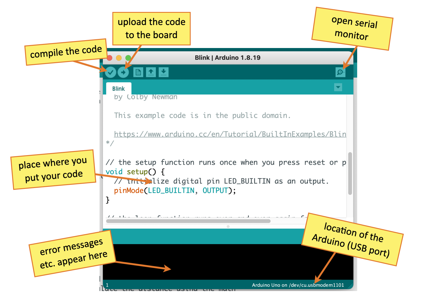
- Have a look at the Arduino IDE, of which you see an image below. Make sure you know and understand the different areas and buttons of this program. It is likely that your Arduino IDE will look somewhat different, depending on the version and on your operating system.
Exercises
Exersise 1: Getting to know the breadboard
During the planairy part, the wiring of the breadboard was explained. For easy reference, see the images below.
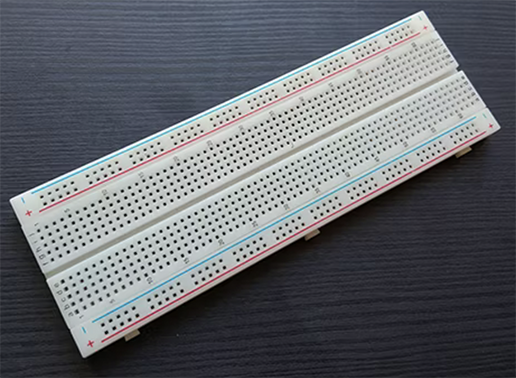
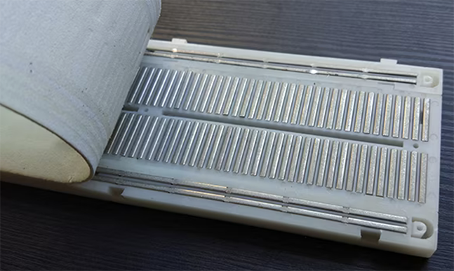
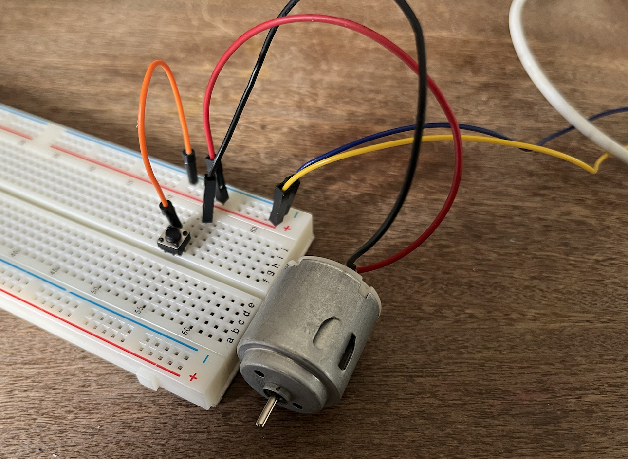
Connect the electromotor to the breadboard, as has been explained in the plenairy part. Make sure that you make use of jump wires to transfer the current from the long lines at the side to the smaller lines orthogonal to these. Add a small switch to the circuit, so that the electromotor only runs when the switch is pressed.
Change the wiring of the electromotor, so that what was previously on the negative pole of the current is now on the positive pole. Do you notice any difference in the rotation of the motor? Why do you think this is?
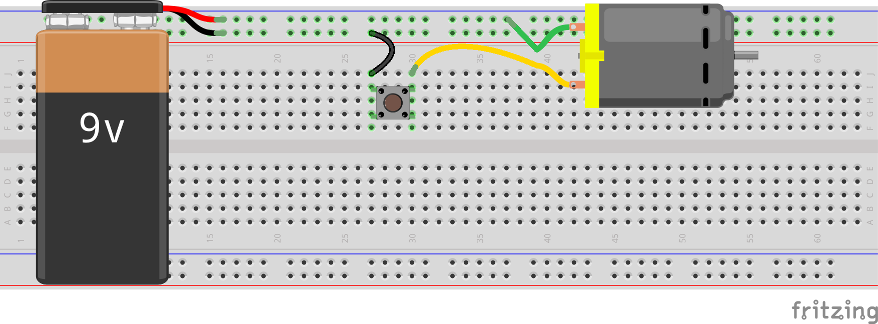
Exercise 2: Adding resistors
In order to control the amount of current over a conductor, we need to add resistors to the circuit. Lots of components don't work well when too much current is applied to it – making them too hot so that they eventually would burn out (as would be the case if you were to put an LED in the previous circuit).
Add a resistor after the switch in your circuit with the electromotor. Do you notice any difference between the workings, when you close the switch? You can determine the resistance of the resistor by looking at its colored bands. Check this site to see how to do that. Note that the direction of the resistor doesn't matter: you can put them either way in the breadboard.

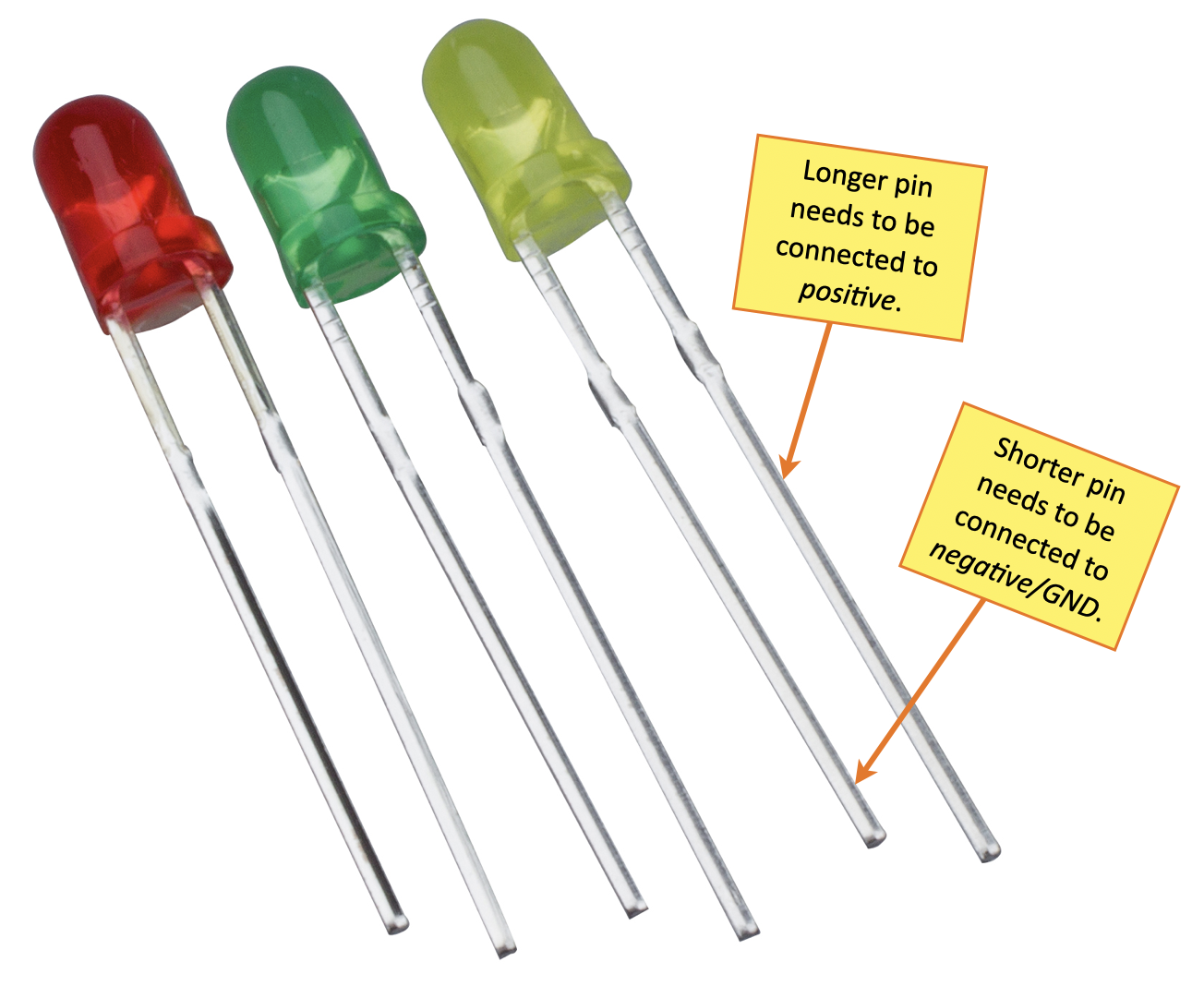
Now we know how to work with resistors, we can work with LEDs insteads of an electromotor – which is visually more attractive, less noisy and easier to do. Clear you breadboard completely and connect one LED with the current, using a resistor of about 150 ohm (the exact amount doesn't matter that much in this point, and is dependent on the voltage of the source). Remember that with LED's, the orientation does matter: the longer pin of the LED should be connected with the positive pole of the power source.
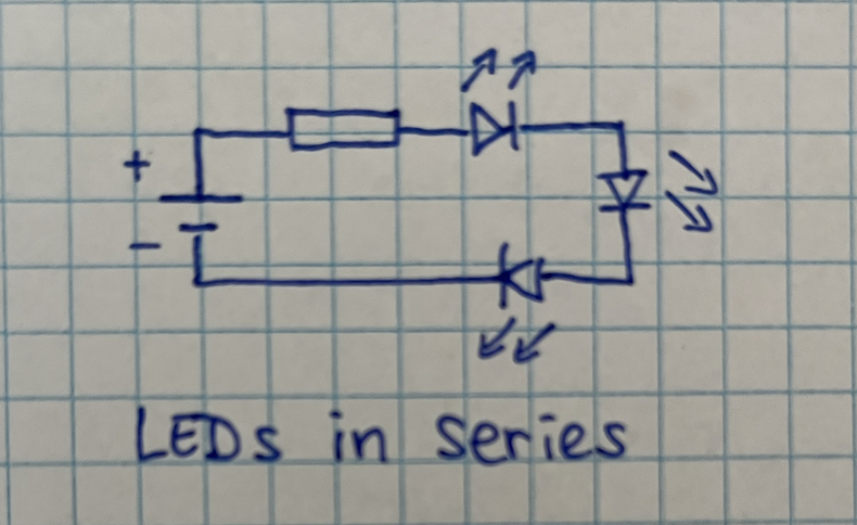
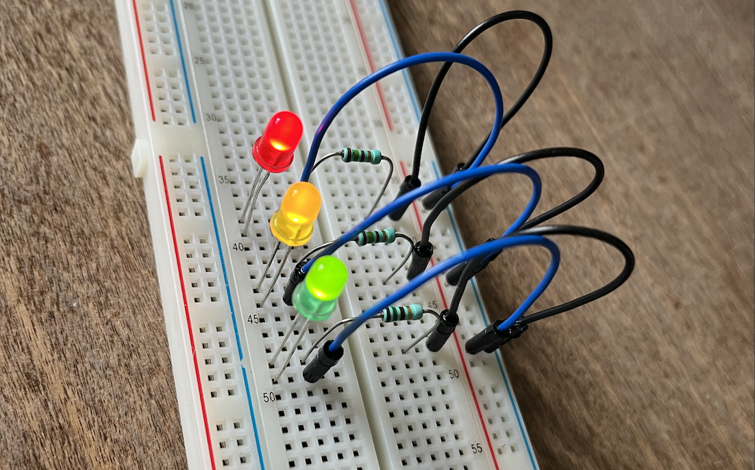
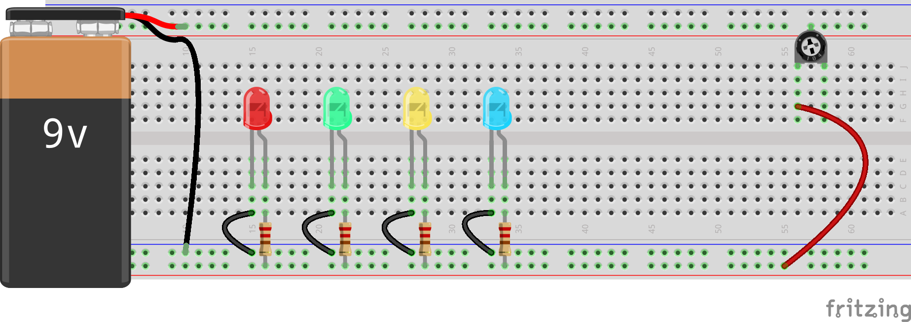
Now, use jump wire to connect multiple LEDs on the breadboard. In general, there are two ways in which you can connect the LEDs to each other: in parallel of in series – have a look a the drawing below. Begin with a few LEDs in series (add a resistor 150 ohm). What happens when you remove one LED from the circuit? Can you explain why that is?
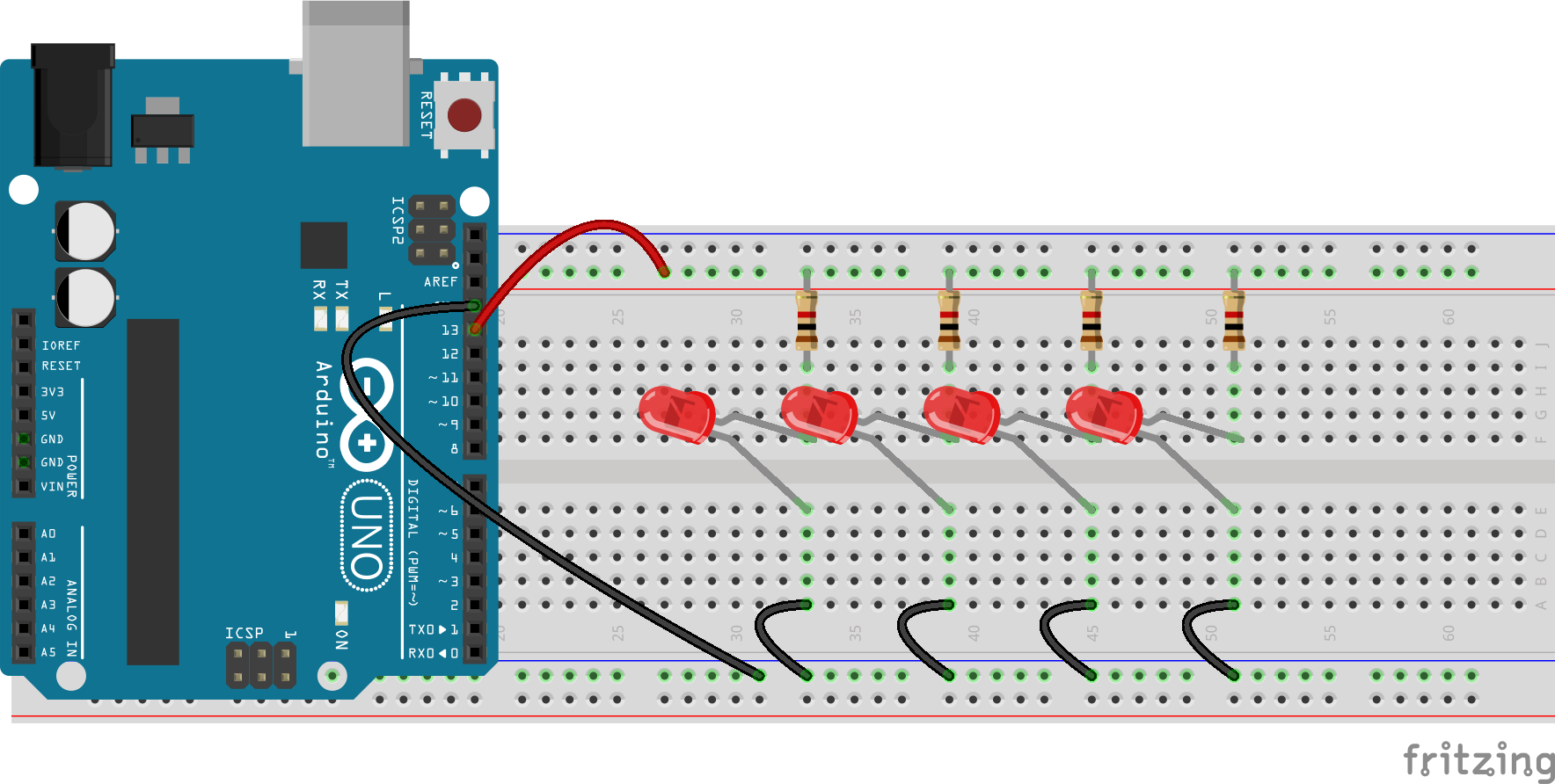
Now, make a new circuit but this time put the LEDs parallel. Make sure that you use individual resistors for each individual LED (if you're interested in why this is needed, check out this explanation by SimplyPut). Now what happens when you remove one of the LEDs of the circuit. Can you explain the difference?

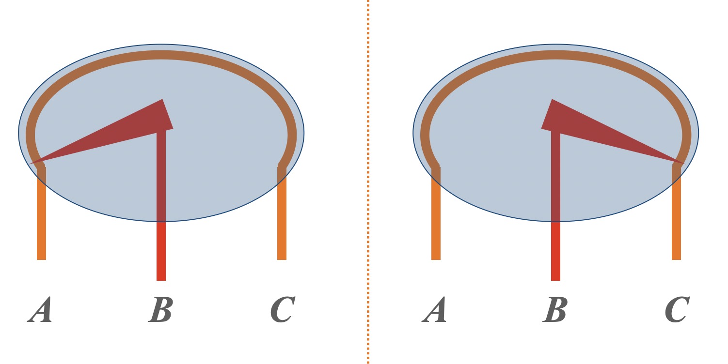
Instead of just a regular resistor, we can also use a variable resistor: this component is like a regular resistor, but with a washer in between so that we can tap in the resistance at any given time. Look at the image below: when the washer is turned completely to the left, all the current from A over B, so nothing is happening at pin C. On the other hand, if the washer is turned completely to the right, all the current needs to go over the complete resisting wire, so almost no current will leave the circuit at pin B.
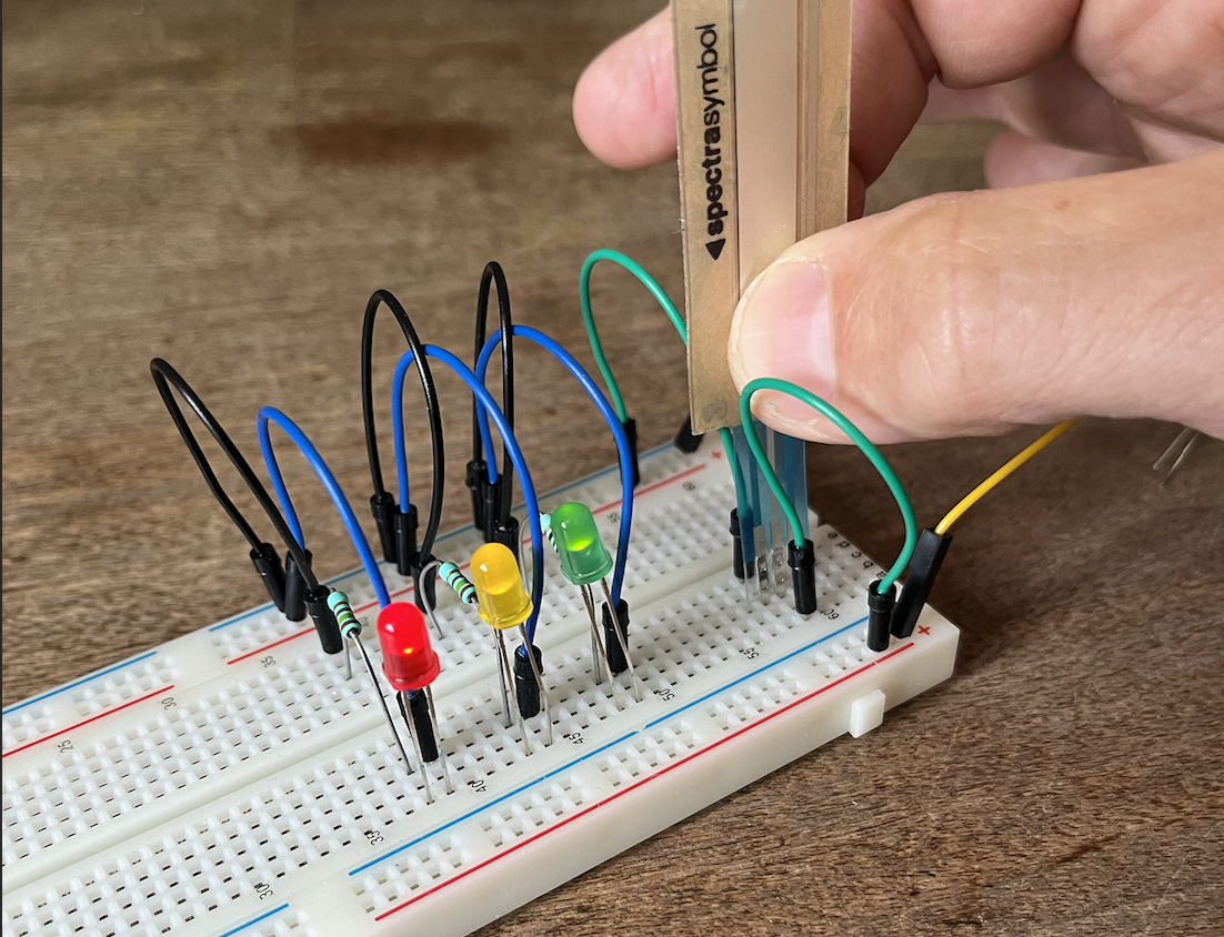
Add a variable restistor between your power supply and the LEDs. You can use a potentiometer for that, but (more interesing) some kind of sensor (several types are available in DAT-space). Experiment with different values of these sensors – do you notice what is happening?
Exercise 3: Basic Arduino
Part 1: expanding on the blinking LED
The Arduino platform has since its start in 2005 grown to become one of the most recognizable brands in the space of electronics and embedded design. Off course, we need to use our breadboard to actually create interesting stuff, as the pins on the Arduino are too few, too narrow and too error prone to be workable.
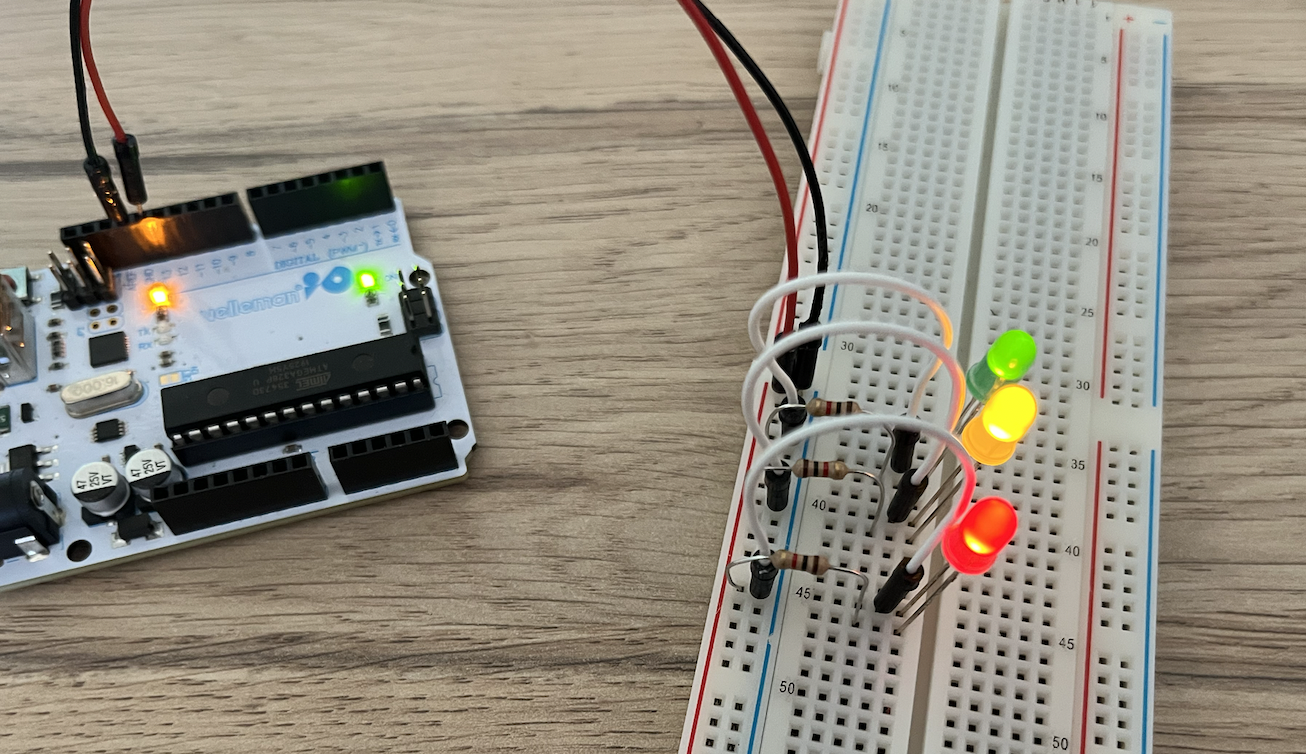
Make sure you have the blinking LED example loaded on your Arduino. As has been explained, the pin that corresponds to the buildin LED is 13. Make use of this knowledge to have a LED on the breadboard blink. Next, add a few more LEDs on the same pin (or port, as they are also called regularly). For a nice effect, you can perhaps use different colors of LEDs.
Adding a push button
Now we are going to add a push button to the circuit so that the LED only blinks when this button is down. We can actually do this in two different ways: we can just use the switch to stop the flow of the current, or we can use some internal logic on the Arduino. The first way is actually quite ease, so we're going to work on the second option.
For this to work, you will need a conditional statement, which we also demonstrated during the plenary part. If you don't remember, have a look at the documentation for conditionals on the Arduino-API, the most important part of which is copied below.
if (condition) {
    //statement(s)
}
Connect the one part of the push button to the \(V_{CC}\) and the other pin to some port on your Arduino. In your setup method, define this pin as input (pinMode(YOUR_PINNR, INPUT;); also have a look at the documentation). Next, have your loop method continously check for the value of the PINNR, using digitalRead(PINNR);. When this value is HIGH, start the blinking.
Have a look at this example to get a basic idea.