Preparation
Last week, we introduced the basic workings of the Arduino. We added LEDs and some potmeters. This week and the next, we are going to have the Arduino communicate with our computer (and vice versa) and for that, we need a communication protocol – USB, in fact.
- Read this article on serial communication at sparkfun.com. You don't have to go over all the stuff, but at least read until you see the headline Wiring and Hardware. Also, don't worry if you do not completely graps everything that is talked about in this article – a small working knowledge of the protocol will be sufficient.
- Have a look at this tutorial on the serial monitor. You don't have to actually make the setup that they are talking about here, as we are going to work on this during this lab class anyway.
- Make sure that you have a possibility to hook up the Arduino on your computer (bring a USB-A to USB-C interface to class if necessary).
- Make sure you have finished and understand all the exercises of week 1.
Exercise 1: The Walking LED
Realise a breadboard with four LEDs in parallel. Have the positive pin of each of the LEDs wired to a different (preferably sequential) port on the Arduino (e.g. pins 4, 5, 6, and 7 - there are some things happening at port 0 and 1, so we usually shy away from using those in a more general setup). Next, create a new Arduino-sketch in which you define all those pins as OUTPUT (you should do this in the setup() method; have a look at the BlinkingLed-example).
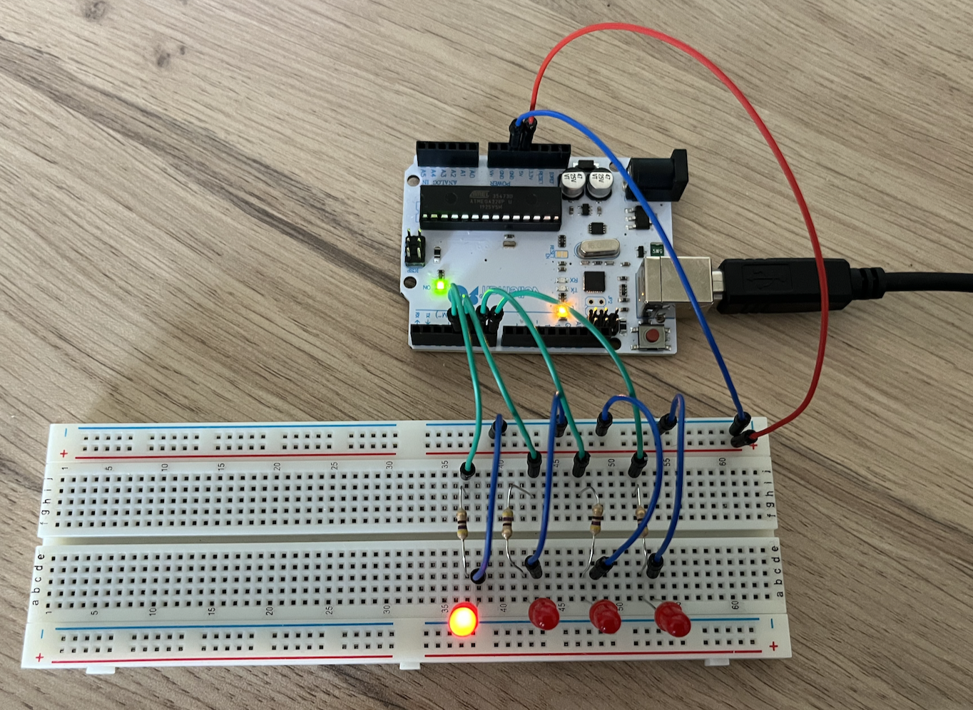
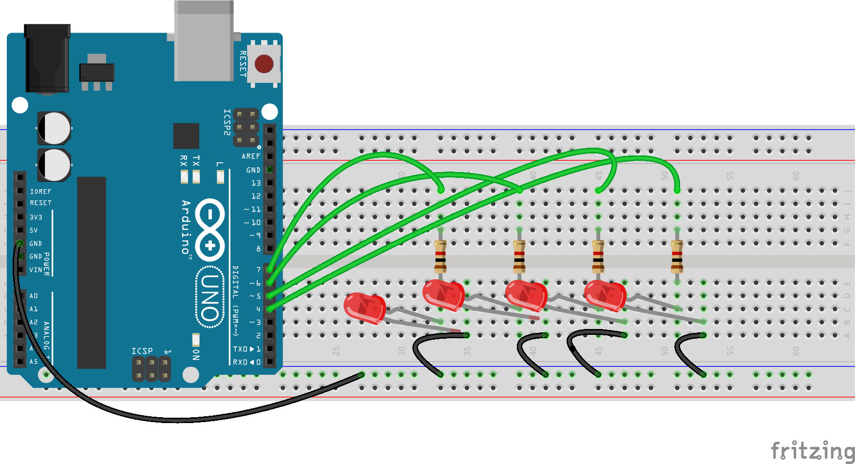
Now, in the loop() method, you should iterate over all those pins and set them to HIGH, wait for a few microseconds, set them to LOW again and repeat the process for the next pin. Have a look at the code below to get an idea of this process:
void loop() {
   digitalWrite(4, HIGH);
   delay(500);
   digitalWrite(4, LOW);
   delay(500);
}
In your loop(), iterate over all the pins that the LEDs are connected to and have every pin switch on and off. If all goes well, you have created a walking light. Can you make this light go back and forth as well? Play around with the value of the call to delay() to get a feeling of the effects of the changes you make.
Exercise 2: Speed things up
Add a variable resistor (a potentiometer) to your breadboard. Connect the external pins to the plus and the minus and the middle pin to an analog input of the Arduino; look at the drawing and the image below to see how to do this.
Next, create a new sketch and copy the code below. If you run this sketch with the serial monitor open, you will see the value that the Arduino is reading from the potentiometer. If you turn the knob of the potmeter, you will notice that the value that it is reading goes from 0 to 1023, while the second parameter is going from 1 to 255 (this is an edited example from Arduino.cc itself).
const int analogInPin = A0;  // Analog input pin that the potentiometer is attached to
  int sensorValue = 0;        // value read from the pot
  int outputValue = 0; // the value we are going to use later on

  void setup() {
    Serial.begin(9600);
  }

  void loop() {
    // read the analog in value:
    sensorValue = analogRead(analogInPin);

    // map it to the range of the analog out:
    outputValue = map(sensorValue, 0, 1023, 0, 255);

    Serial.print("sensor = ");
    Serial.print(sensorValue);
    Serial.print("\t output = ");
    Serial.println(outputValue);

    delay(2);
  }
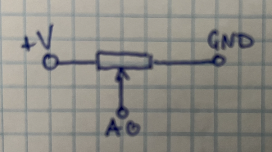
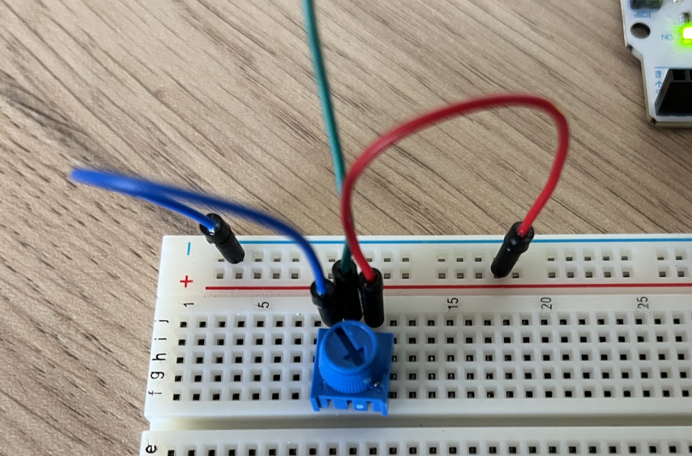
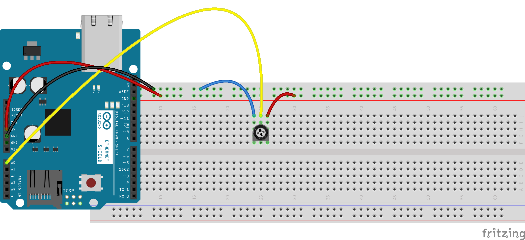
Now integrate the code above to your walking light code, so that it changes the value of the call to delay() in your walking light. Have the Arduino read and map the value of the potentiometer on every loop; if all goes well, you are now able to change the speed with which the LEDs are 'walking' by changing the value of the potentiometer.
Exercise 3: more input, more interaction
Double the amount of LEDs on your breadboard, in such a way that instead of one we always have two LEDs shining in unisono. Now add a push-button to your circuit so that this second array of LEDs will only work when this button is pressed. Again, you can do this in two ways, one hardware and one software (just like in exercise 3 of last week). However, it is actually more difficult to do so on the Arduino site...
First, do it with the hardware only. Add the push-button to your breadboard and create a circuit so that the second array is dependent on the state of the push-button. Make a schematic drawing of you elaboration - we will talk over this in a plenairy setting.
For the second part, connect the second array of LEDs to four other ports of you Arduino and re-create the functionality above (to with the push-button). This time, you will need to change the Arduino-code.
Exercise 4: Sensing the distance
Part 1
Most sensors work just like a complex potentiometer, with three pins and the middle pin corresponding to the washer of the property being sensed: light, humidity, sound-volume, heat, ... However, there are also lots of sensors that have four (or even more) pins. In this exercise, we are looking at one of those: the distance sensor.
Please refer to the first image below. As you can see, the first and last pin are the by now familiar plus and ground pins. However, the second and third pin work somewhat different.
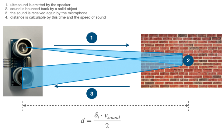
The distance sensor actually consists of a very small speaker and a very small microphone. When you put power to the speaker, it releases a sound of a specific frequency (about 40kHz, so you won't be able to hear it – that's why it's called 'ultrasound'). When you put power to the microphone, it starts listening to the same frequency as the speaker is transmitting. So if you know when the speaker starts tranmitting and you know when the microphone is picking up the sound, you can calculate the distance between the device and some solid object
See the images below to get an idea of how this works. Please note that the pin-numbers at the drawing on the left are arbitrary: they of course depend only on the code that you put on the Arduino.
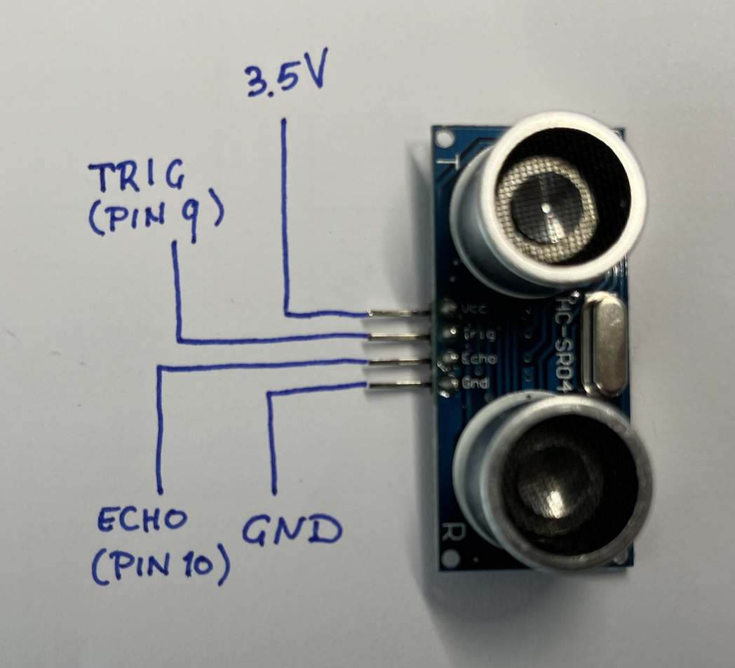
During the plenary part, a short description is given how to work with this distance sensor. Realise this on your breadboard and have the found distance printed in the Serial Monitor. Have a look at this description to get started with the exercise. Next, use the distance-sensor to have the speed of your walking LEDs depend on the distance that the sensor is giving.
Part 2
In your kit you will find a three-color LED. Have a look at the image below to understand how this works. Add this LED to your construction and make it so that the measured distance is also reflected in the color of the LED (e.g. RED if someone is too close and GREEN is someone is far away). Please note that the speed of the walking light (part 1 of this exercise) should still run (so this should be an addition).
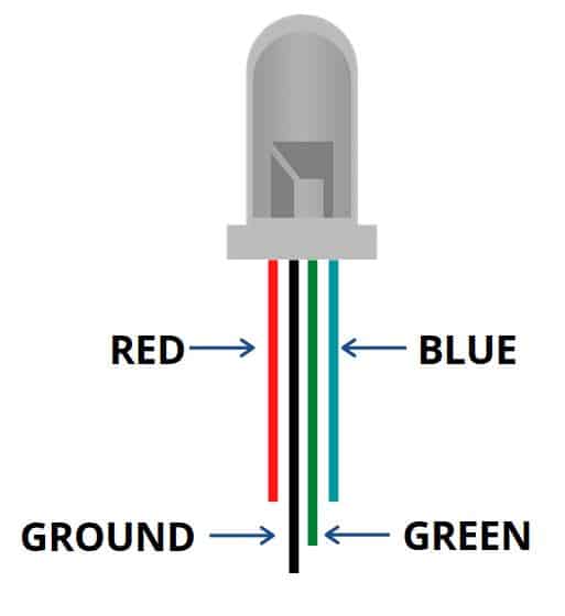
We will expand on this example next week.
Assignment: solder an electronic sculpture
Until now, we have done all of our work on the breadboard. This is perfect for quick experimenting and rapid prototyping, but in real life you probably want to solder the components together: this makes your work more robust and permanent.
Obviously, esthetics is seldom a requirement for such an electronic circuit (a notable exception is formed by the (early) Macintosh computers, whose electronic boards were as thoroughly designed as the more visible parts of the hardware). However, in this assignment we are going to make a beautiful and (more of less) functional sculpture.
We did some soldering during class; now it is up to you to make a nice sculpture using at least LEDs, resistors and a battery. Make sure that the circuit you make actually works, but solder it together so that looks nice. You could just make a simple lamp (such as the one we showed during class), or make it more interesing using some active components.
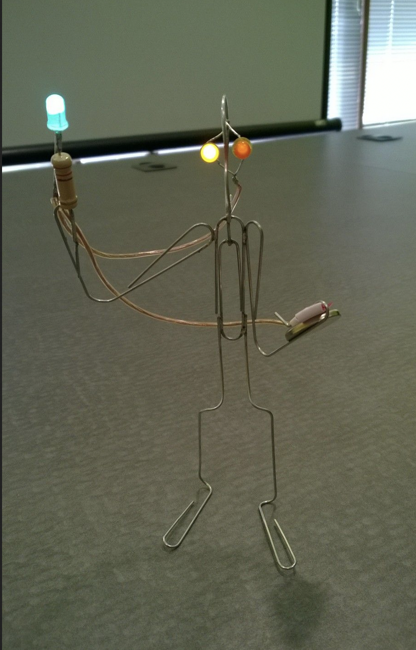
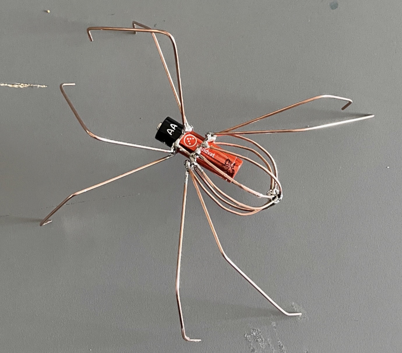
This week, you can go to the electronics lab for help and assistance on this assignment. We will look at your elaborations at the beginning of the next class (before we start with the next topics).